Vickers Style
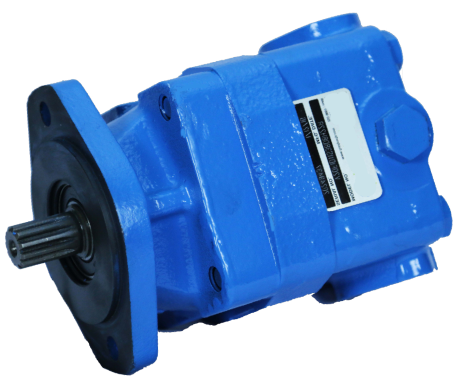
How to order
V 20 F-1 P 13 S-1 A 8H 22-(***)-L
- V
- Vane pump
- 20
- Series
- F
- Integral valve options
- 1
- Mounting
- P
- Inlet port connections
- 13
- SAE rated capacity
- S
- Outlet port connections
- 1
- Shaft
- A
- Outlet port position
- 8H
- Integral valves
- 22
- Design
- ***
- Special suffix
- L
- Shaft rotation
1. Vane pump
V — vane pump.
2. Series
10 or 20.
3. Integral valve options
Omit if not required.
| Code | Description |
|---|---|
| F | Flow control and relief |
| P | Priority valve and relief |
| NF | Flow control and relief with internal drain |
4. Mounting
| Code | Description |
|---|---|
| 1 | 2-bolt flange |
| 6 | 2-bolt flange (SAE “B” size) |
5. Inlet port connections
| Code | Description |
|---|---|
| D | 1 5/16-12 straight thread (V20 only) |
| P | 1" NPT thread (V10 only). 1 1/4" NPT thread (V20 only) |
| S | 1 5/16-12 straight thread (V10 only). 1 5/8"-12 straight thread (V20 only) |
| T | 1 3/16-12 straight thread (V10 only) |
6. SAE rated capacity — USgpm
At 1,200 r/min and 100 psi.
| Code | V10 series |
|---|---|
| 1 | 4 L/min (1 USgpm) |
| 2 | 8 L/min (2 USgpm) |
| 3 | 11 L/min (3 USgpm) |
| 4 | 15 L/min (4 USgpm) |
| 5 | 19 L/min (5 USgpm) |
| 6 | 23 L/min (6 USgpm) |
| 7 | 27 L/min (7 USgpm) |
| Code | V20 series |
|---|---|
| 6 | 23 L/min (6 USgpm) |
| 7 | 27 L/min (7 USgpm) |
| 8 | 30 L/min (8 USgpm) |
| 9 | 34 L/min (9 USgpm) |
| 10 | 39 L/min (10 USgpm) |
| 11 | 42 L/min (11 USgpm) |
| 12 | 45 L/min (12 USgpm) |
| 13 | 49 L/min (13 USgpm) |
7. Outlet port connections
| Code | Standard cover | Flow control cover | Priority valve cover | |||
|---|---|---|---|---|---|---|
| Pressure | Tank | Primary outlet | Secondary outlet | Tank | ||
| K | — | — | — | 9/16-18 straight thread (V10P) | 3/4-16 straight thread (V10P) | 9/16-18 straight thread (V10P) |
| P | 1/2" NPT (V10 only) | — | — | — | — | — |
| 3/4" NPT (V20 only) | 3/4-16 straight thread (V10F and V20F) | 1/2" NPT (V10F and V20F) | — | — | — | |
| R | 1-1/16"-12 straight thread (V10 only) | — | — | — | — | — |
| 1-3/16"-12 straight thread (V20 only) | — | — | — | — | — | |
| S | 3/4"-16 straight thread (V10 only) | — | — | — | — | — |
| 1-1/16"-12 straight thread (V20 only) | 3/4-16 straight thread (V20F) | 1-1/16"-12 straight thread (V20F) | — | — | — | |
| T NF option only | — | 3/4-16 straight thread (V10F) | 3/4-16 straight thread (V10F) | 3/4-16 straight thread (V20P) | 7/8-14 straight thread (V20P) | 3/4-16 straight thread (V20P) |
| — | 3/4-16 straight thread (V10NF and V20NF) | — | — | — | — | |
8. Shafts
| Code | Description |
|---|---|
| 1 | Straight keyed |
| 3 | Threaded with Woodruff key |
| 11 | Splined |
| 12 | Splined (V10 only) |
| 38 | Splined |
| 62 | SAE A spline (V20 only) |
9. Outlet port position, or primary outlet port position
Viewed from the pump cover end.
| Code | Position |
|---|---|
| A | Opposite the inlet port |
| B | 90° counterclockwise from the inlet |
| C | In line with the inlet |
| D | 90° clockwise from the inlet |
10. Integral valves
Example 8H combines flow 8 with relief setting H.
| Code | Flow |
|---|---|
| 2 | 8 L/min (2 USgpm) |
| 3 | 11 L/min (3 USgpm) |
| 4 | 15 L/min (4 USgpm) |
| 5 | 19 L/min (5 USgpm) |
| 6 | 23 L/min (6 USgpm) |
| 7 | 27 L/min (7 USgpm) |
| 8 | 30 L/min (8 USgpm) |
| Code | Relief valve setting |
|---|---|
| A | 17 bar (250 psi) |
| B | 35 bar (500 psi) |
| C | 52 bar (750 psi) |
| D | 70 bar (1000 psi) |
| E | 86 bar (1250 psi) |
| F | 100 bar (1500 psi) |
| G | 121 bar (1750 psi) |
| H | 140 bar (2000 psi) |
| J | 155 bar (2250 psi) |
| K | 175 bar (2500 psi) |
| L | 190 bar (2750 psi) |
| 0 | Custom setting (indicated by the suffix) |
11. Design
Subject to change. Installation dimensions stay the same for designs –20 through –29.
12. Special suffix feature
Omit if not required.
13. Shaft rotation
Viewed from the pump shaft end.
| Code | Rotation |
|---|---|
| L | Left hand, counterclockwise |
| R | Right hand, or omit |
*All manufacturer names and part numbers are used for reference only.
Single pump operating specifications
| Model series | Flow USgpm at 1,200 r/min and 7 bar (100 psi) | Displacement cm³/r (in³/r) | Max. r/min | Max. bar (psi) | Typical flow L/min (USgpm) at max speed and pressure | Typical input power kW (hp) at max speed and pressure | Weight kg (lb) |
|---|---|---|---|---|---|---|---|
| 1 | 3.3 (.20) | 4800 | 172 (2500) | 13.6 (3.6) | 5.2 (7) | 4.5 – 6.8 (10 – 15) | |
| 2 | 6.6 (.40) | 4500 | 172 (2500) | 27.7 (7.3) | 10.1 (13.6) | ||
| V10 | 3 | 9.8 (.60) | 4000 | 172 (2500) | 35.6 (9.4) | 13.3 (17.8) | |
| V10(N)F | 4 | 13.1 (.80) | 3400 | 172 (2500) | 41.3 (10.9) | 15.2 (20.4) | |
| V10P | 5 | 16.4 (1.00) | 3200 | 172 (2500) | 48.5 (12.8) | 17 (22.8) | |
| 6 | 19.5 (1.19) | 3000 | 152 (2200) | 55.3 (14.6) | 18.3 (24.5) | ||
| 7 | 22.8 (1.39) | 2800 | 138 (2000) | 60.6 (16) | 17.9 (24) | ||
| 6 | 19.5 (1.19) | 3400 | 172 (2500) | 61.0 (16.1) | 21.6 (29) | 7.3 – 8.2 (16 – 18) | |
| 7 | 22.8 (1.39) | 3000 | 172 (2500) | 63.3 (16.7) | 22 (29.5) | ||
| V20 | 8 | 26.6 (1.62) | 2800 | 172 (2500) | 67.1 (17.7) | 24.2 (32.5) | |
| V20F | 9 | 29.7 (1.81) | 2800 | 172 (2500) | 75.0 (19.8) | 26.5 (35.5) | |
| V20NF | 10 | 31.5 (1.93) | 2500 | 172 (2500) | 81.0 (21.4) | 27.3 (36.6) | |
| V20P | 11 | 36.4 (2.22) | 2500 | 172 (2500) | 86.8 (22.9) | 28 (37.5) | |
| 12 | 39.0 (2.38) | 2400 | 152 (2200) | 87.2 (23) | 26.8 (36) | ||
| 13 | 42.5 (2.59) | 2400 | 152 (2200) | 98.1 (25.9) | 29.1 (39) |
Note: The applicable equations and start-up procedures are at the end of the document.
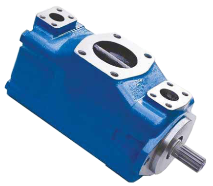
How to order
(F3) 20V (M) 11 A (M) (F) 1 A 22 R ***
- F3
- Viton seals
- 20V
- Series
- M
- Pilot designation
- 11
- Geometric displacement
- A
- Port connections
- M
- Port connection modifier
- F
- Mounting
- 1
- Shaft
- A
- Outlet position
- 22
- Design
- R
- Rotation
- ***
- Special suffix
1. Viton seals
F3 — Viton seals. Omit if not required.
2. Series
| Series | Displacement |
|---|---|
| 20V | 7 to 45 cm³/r (0.43 to 2.78 in³/r) |
| 25V | 33 to 67 cm³/r (2.0 to 4.1 in³/r) |
| 35V | 81 to 121 cm³/r (4.9 to 7.4 in³/r) |
| 45V | 138 to 193 cm³/r (8.4 to 11.6 in³/r) |
3. Pilot designation
| Code | Description |
|---|---|
| Omit | Standard pilot |
| S | SAE per ISO 3019/1 (SAE J744). Does not apply to the 20V pump |
| M | Metric per ISO 3019/2. Codes 100A2HW. Does not apply to the 20V pump |
4. Geometric displacement
Rated capacity (USgpm) at 1,200 r/min and 6.9 bar (100 psi).
| Frame size | Code (USgpm) | cm³/r | in³/r |
|---|---|---|---|
| 20V | 2 | 7 | 0.43 |
| 5 | 18 | 1.10 | |
| 8 | 27 | 1.67 | |
| 9 | 30 | 1.85 | |
| 11 | 36 | 2.22 | |
| 12 | 40 | 2.47 | |
| 14 | 45 | 2.78 | |
| 25V | 10 | 33 | 2.01 |
| 12 | 39 | 2.47 | |
| 14 | 45 | 2.78 | |
| 17 | 55 | 3.39 | |
| 21 | 67 | 4.13 | |
| 35V | 25 | 81 | 4.94 |
| 30 | 97 | 5.91 | |
| 35 | 112 | 6.83 | |
| 38 | 121 | 7.37 | |
| 45V | 42 | 138 | 8.41 |
| 45 | 147 | 8.95 | |
| 50 | 162 | 9.85 | |
| 60 | 193 | 11.75 |
5. Port connections
A — SAE 4-bolt flange.
6. Port connection modifier
| Code | Description |
|---|---|
| Omit | Inch-thread port connection (4-bolt flange) |
| M | Metric port connection (4-bolt flange). Does not apply to 20V |
7. Mounting
| Code | Description |
|---|---|
| Omit | Flange mounting |
| F | Foot mounting |
8. Shafts
Standard pilot shafts.
| Model | Straight key | Heavy-duty straight key | Metric straight key | Splined |
|---|---|---|---|---|
| 20V | 1 | N/A | N/A | 151 |
| 20V–45V | 1 | 86 | N/A | 11 |
| 25VS–45VS | 202 | 203 | N/A | 297 |
| 25VM–45VM | N/A | N/A | 292N | N/A |
SAE “S” pilot shafts and ISO metric “M” shafts.
9. Outlet positions
Viewed from the pump cover end.
| Code | Description |
|---|---|
| A | Opposite the inlet port |
| B | 90° counterclockwise from the inlet |
| C | In line with the inlet |
| D | 90° clockwise from the inlet |
10. Design
The example shows 22.
11. Rotation
Viewed from the pump shaft end.
| Code | Description |
|---|---|
| R | Right hand (clockwise) |
| L | Left hand (counterclockwise) |
12. Special suffix
Contact our sales team for other options, including shafts, ports, displacements and mountings.
*All manufacturer names and part numbers are used for reference only.
How to order
(F3) 2520V (M) 10 A 7 (F) 1 AA 22 R
- F3
- Viton seals
- 2520V
- Series
- M
- Pilot designation
- 10
- Shaft-end displacement
- A
- Port connections
- 7
- Cover-end displacement
- F
- Mounting
- 1
- Shaft
- AA
- Port orientation
- 22
- Design
- R
- Rotation
1. Viton seals
F3 — Viton seals. Omit if not required.
2. Series
Displacements in cm³/r (in³/r).
| Model | Shaft end | Cover end |
|---|---|---|
| 2520V | 33 to 67 cm³/r (2.0 to 4.1 in³/r) | 7 to 45 cm³/r (0.45 to 2.8 in³/r) |
| 2525V | 33 to 67 cm³/r (2.0 to 4.1 in³/r) | 33 to 67 cm³/r (2.0 to 4.1 in³/r) |
| 3520V | 81 to 121 cm³/r (4.9 to 7.4 in³/r) | 7 to 45 cm³/r (0.45 to 2.8 in³/r) |
| 3525V | 81 to 121 cm³/r (4.9 to 7.4 in³/r) | 33 to 67 cm³/r (2.0 to 4.1 in³/r) |
| 4520V | 138 to 193 cm³/r (8.4 to 11.8 in³/r) | 7 to 45 cm³/r (0.45 to 2.8 in³/r) |
| 4525V | 138 to 193 cm³/r (8.4 to 11.8 in³/r) | 33 to 67 cm³/r (2.0 to 4.1 in³/r) |
| 4535V | 138 to 193 cm³/r (8.4 to 11.8 in³/r) | 81 to 121 cm³/r (4.9 to 7.4 in³/r) |
3. Pilot designation
| Code | Description |
|---|---|
| Omit | Standard pilot |
| S | SAE per ISO 3019/1 (SAE J744). Does not apply to 2525V |
| M | Metric per ISO 3019/2. Codes 100A2HW. Does not apply to 2525V |
4. Geometric displacement — shaft end
Rated capacity (USgpm) at 1,200 r/min and 6.9 bar (100 psi).
| Frame size | Code (USgpm) | cm³/r | in³/r |
|---|---|---|---|
| 25**V | 10 | 33 | 2.0 |
| 12 | 40 | 2.5 | |
| 14 | 45 | 2.8 | |
| 17 | 55 | 3.4 | |
| 21 | 67 | 4.1 | |
| 35**V | 25 | 81 | 4.9 |
| 30 | 97 | 5.9 | |
| 35 | 112 | 6.8 | |
| 38 | 121 | 7.4 | |
| 45**V | 42 | 138 | 8.4 |
| 45 | 147 | 9.0 | |
| 50 | 162 | 9.9 | |
| 60 | 193 | 11.8 |
5. Port connections
A — SAE 4-bolt flange.
6. Geometric displacement — cover end
Rated capacity (USgpm) at 1,200 r/min and 6.9 bar (100 psi).
| Frame size | Code (USgpm) | cm³/r | in³/r |
|---|---|---|---|
| **20V | 2 | 7 | 0.43 |
| 5 | 18 | 1.1 | |
| 8 | 27 | 1.7 | |
| 9 | 30 | 1.9 | |
| 11 | 36 | 2.2 | |
| 12 | 40 | 2.5 | |
| 14 | 45 | 2.8 | |
| **25V | 10 | 33 | 2.0 |
| 12 | 40 | 2.5 | |
| 14 | 45 | 2.8 | |
| 17 | 55 | 3.4 | |
| 21 | 67 | 4.1 | |
| 4535V | 25 | 81 | 4.9 |
| 30 | 97 | 5.9 | |
| 35 | 112 | 6.8 | |
| 38 | 121 | 7.4 |
7. Mounting
| Code | Description |
|---|---|
| Omit | Flange mounting |
| F | Foot mounting |
8. Shafts
Standard pilot shafts.
| Model | Straight key | Heavy-duty straight key | Metric straight key | Splined |
|---|---|---|---|---|
| 25**V–45**V | 1, 86 | N/A | N/A | 11 |
| 25**VS–45**VS | 202 | 203 | N/A | 297 |
| 25**VM–45**VM | N/A | N/A | 292N | N/A |
SAE “S” pilot shafts and ISO metric “M” shafts.
Contact our sales team for other options, including shafts, ports, displacements and mountings.
9. Port orientation
Viewed from the pump cover end.
All series except 2525V and 4535V.
| Code | Outlet no. 1 | Outlet no. 2 |
|---|---|---|
| AA | Opposite the inlet | 135° counterclockwise from the inlet |
| AB | Opposite the inlet | 45° counterclockwise from the inlet |
| AC | Opposite the inlet | 45° clockwise from the inlet |
| AD | Opposite the inlet | 135° clockwise from the inlet |
| BA | 90° counterclockwise from the inlet | 135° counterclockwise from the inlet |
| BB | 90° counterclockwise from the inlet | 45° counterclockwise from the inlet |
| BC | 90° counterclockwise from the inlet | 45° clockwise from the inlet |
| BD | 90° counterclockwise from the inlet | 135° clockwise from the inlet |
| CA | In line with the inlet | 135° counterclockwise from the inlet |
| CB | In line with the inlet | 45° counterclockwise from the inlet |
| CC | In line with the inlet | 45° clockwise from the inlet |
| CD | In line with the inlet | 135° clockwise from the inlet |
| DA | 90° clockwise from the inlet | 135° counterclockwise from the inlet |
| DB | 90° clockwise from the inlet | 45° counterclockwise from the inlet |
| DC | 90° clockwise from the inlet | 45° clockwise from the inlet |
| DD | 90° clockwise from the inlet | 135° clockwise from the inlet |
2525V and 4535V series.
| Code | Outlet no. 1 | Outlet no. 2 |
|---|---|---|
| AA | Opposite the inlet | Opposite the inlet |
| AB | Opposite the inlet | 90° counterclockwise from the inlet |
| AC | Opposite the inlet | In line with the inlet |
| AD | Opposite the inlet | 90° clockwise from the inlet |
| BA | 90° counterclockwise from the inlet | Opposite the inlet |
| BB | 90° counterclockwise from the inlet | 90° counterclockwise from the inlet |
| BC | 90° counterclockwise from the inlet | In line with the inlet |
| BD | 90° counterclockwise from the inlet | 90° clockwise from the inlet |
| CA | In line with the inlet | Opposite the inlet |
| CB | In line with the inlet | 90° counterclockwise from the inlet |
| CC | In line with the inlet | In line with the inlet |
| CD | In line with the inlet | 90° clockwise from the inlet |
| DA | 90° clockwise from the inlet | Opposite the inlet |
| DB | 90° clockwise from the inlet | 90° counterclockwise from the inlet |
| DC | 90° clockwise from the inlet | In line with the inlet |
| DD | 90° clockwise from the inlet | 90° clockwise from the inlet |
10. Design
The example shows 22.
11. Rotation
Viewed from the pump shaft end.
| Code | Description |
|---|---|
| R | Right hand (clockwise) |
| L | Left hand (counterclockwise) |
*All manufacturer names and part numbers are used for reference only.
How to order
2520VQ S V10 S 17 A 11 S 5 S 297 BCA 3 D 20 R
- 2520VQ
- Series
- S
- SAE mounting
- V10
- Single pump series
- S
- V10 cover options
- 17
- Shaft-end flow
- A
- Port connections
- 11
- Center pump flow
- S
- Shaft seal
- 5
- Cover-end flow
- S
- No. 3 outlet connection
- 297
- Splined shaft
- BCA
- Outlet positions
- 3
- Controlled flow
- D
- Relief valve setting
- 20
- Design
- R
- Rotation
1. Series
| Series |
|---|
| 2520V(Q) |
| 3520V(Q) |
| 3525V(Q) |
| 4525V(Q) |
| 4535V(Q) |
2. SAE mounting
S — SAE mounting per J744 101-2.
3. Single pump series
Cover-end pump of the triple pump. The example shows V10.
4. V10 pump cover options
| Code | Description |
|---|---|
| S | Standard cover |
| F | Integral flow control and relief valve |
| P | Integral priority and relief valve |
5. SAE rated flow — shaft end
Rated flow at 1,200 r/min and 100 psi (in³/r).
| Series | USgpm | in³/r |
|---|---|---|
| 2520V(Q) | 10 | 2.01 |
| 12 | 2.41 | |
| 14 | 2.80 | |
| 17 | 3.37 | |
| 19 | 3.89 | |
| 21 | 4.12 | |
| 3525V(Q) | 21 | 4.12 |
| 25 | 4.98 | |
| 30 | 5.96 | |
| 35 | 6.88 | |
| 38 | 7.42 | |
| 4535V(Q) | 42 | 8.46 |
| 45 | 8.89 | |
| 47 | 9.33 | |
| 50 | 9.90 | |
| 57 | 11.33 | |
| 60 | 11.80 |
6. Double pump port connections
| Code | Description |
|---|---|
| A | SAE 4-bolt flange on all ports |
| C | SAE 4-bolt flange inlet and SAE thread outlet. 2520VQSV10 only |
7. SAE rated flow — center pump
Rated flow at 1,200 r/min and 100 psi (in³/r).
| Series | USgpm | in³/r |
|---|---|---|
| **20V(Q) | 2 | .39 |
| 5 | 1.10 | |
| 6 | 1.19 | |
| 8 | 1.67 | |
| 9 | 1.81 | |
| 11 | 2.22 | |
| 12 | 2.41 | |
| 14 | 2.80 | |
| **25V(Q) | 10 | 2.01 |
| 12 | 2.41 | |
| 14 | 2.80 | |
| 17 | 3.37 | |
| 19 | 3.89 | |
| 21 | 4.12 | |
| **35V(Q) | 21 | 4.12 |
| 25 | 4.98 | |
| 30 | 5.96 | |
| 35 | 6.88 | |
| 38 | 7.42 |
8. Shaft seal
| Code | Description |
|---|---|
| S | Double seal |
| Omit | Single seal |
9. SAE rated flow — cover end
Rated flow at 1,200 r/min and 100 psi (in³/r).
| Series | USgpm | in³/r |
|---|---|---|
| V10 | 1 | .20 |
| 2 | .40 | |
| 3 | .60 | |
| 4 | .80 | |
| 5 | 1.00 | |
| 6 | 1.19 | |
| 7 | 1.39 |
10. No. 3 outlet port connection
Standard cover.
| Code | Description | Series |
|---|---|---|
| S | Flow control cover with .750-16 straight thread | V10 |
| T | .750-16 straight thread, control port and tank port | V10F |
| K | .563-18 straight thread on the primary port and the tank port. Secondary port with .750-16 straight thread | V10P |
11. Splined shaft
| Code | Description |
|---|---|
| 297 | VQS only |
| 298 | VQS only |
| 77 | 2520VQ V10 only |
12. Position of outlets no. 1, 2 and 3
Viewed from the cover end.
| Position | Outlet no. 1 | Outlet no. 2 | Outlet no. 3 |
|---|---|---|---|
| Opposite the inlet | A | A (4535 only) | A |
| 135° counterclockwise from the inlet | — | A | — |
| 90° counterclockwise from the inlet | B | B (4535V only) | B |
| 45° counterclockwise from the inlet | — | B | — |
| In line with the inlet | C | C (4535 only) | C |
| 45° clockwise from the inlet | — | C | — |
| 90° clockwise from the inlet | D | D (4535 only) | D |
| 135° clockwise from the inlet | — | D | — |
13. Controlled flow, V10F and V10P
in³/r.
| Series | USgpm | in³/r |
|---|---|---|
| V10F and V10P | 3 | .60 |
| 4 | .80 | |
| 5 | 1.00 | |
| 6 | 1.19 | |
| 7 | 1.39 |
14. Relief valve setting, V10F and V10P
| Code | Setting |
|---|---|
| A | 17 bar (250 psi) |
| B | 35 bar (500 psi) |
| C | 52 bar (750 psi) |
| D | 70 bar (1000 psi) |
| E | 86 bar (1250 psi) |
| F | 100 bar (1500 psi) |
| G | 121 bar (1750 psi) |
| H | 140 bar (2000 psi) |
| J | 155 bar (2250 psi) |
| K | 175 bar (2500 psi) |
15. Design
The example shows 20.
16. Shaft rotation
Viewed from the pump shaft end.
| Code | Description |
|---|---|
| R | Right hand (clockwise) |
| L | Left hand (counterclockwise) |
*All manufacturer names and part numbers are used for reference only.
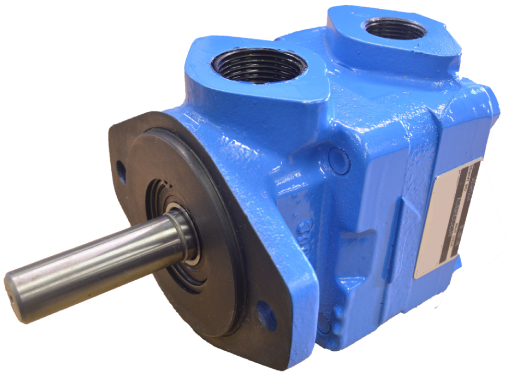
How to order
- F3
- Special seals
- V
- Vane type
- 2
- Series
- 10
- Body type
- 2
- Rated capacity
- 1
- Shaft
- C
- Outlet position
- 12
- Design
- S214
- Special features
- LH
- Rotation
1. Special seals
F3 — synthetic fluids. Omit if not required.
2. Vane type
V — vane pump.
3. Series
The example shows 2.
4. Body type
| Code | Description |
|---|---|
| 10 | Flange mounting |
| 14 | Foot mounting |
| 30 | Face mounting |
For the foot bracket kit separately, order model FB-A-10.
5. Rated capacity
At 1,200 r/min and 100 psi.
| Code | Flow |
|---|---|
| 2 | 2 gpm (0.39 in³) |
| 3 | 3 gpm (0.58 in³) |
| 5 | 5 gpm (0.96 in³) |
| 6 | 6 gpm (1.16 in³) |
| 8 | 8 gpm (1.54 in³) |
| 8W | 8 gpm (1.54 in³) |
| 9W | 9 gpm (1.73 in³) |
| 11 | 11 gpm (2.12 in³) |
| 11W | 11 gpm (2.12 in³) |
6. Shaft
| Code | Description |
|---|---|
| 1 | Straight key (standard) |
| 3 | Threaded straight key |
| 11 | 11-tooth spline |
Other shafts are available on request.
7. Outlet position
Viewed from the cover end.
| Code | Description |
|---|---|
| A | Outlet opposite the inlet |
| B | Outlet 90° counterclockwise from the inlet |
| C | Outlet in line with the inlet |
| D | Outlet 90° clockwise from the inlet |
8. Design
Subject to change. Installation dimensions stay as shown for designs 10 through 19.
12 — current design.
9. Special features
| Code | Outlet | Inlet |
|---|---|---|
| STD / S7 / S49 / S85 | 1/2" NPT | 1" NPT |
| S63 / S214 | 3/4" NPT | 1" NPT |
| S89 / S90 | 7/8-14 O-ring | 1" NPT |
| S82 / S86 | 7/8-14 O-ring | 2-bolt flange |
Includes the other matching changes.
10. Rotation
Viewed facing the shaft end.
LH — left-hand rotation. Omit for right-hand rotation.
Operating data
Weight.
| Mounting | Weight |
|---|---|
| Flange | 18 lb |
| Foot | 23 lb |
| Face | 18 lb |
Maximum speed (r/min), by fluid.
| Fluid | r/min |
|---|---|
| Petroleum oil | 1800 |
| Synthetic | 1200–1800 |
| Water-containing | 1800 |
Maximum pressure (psi), by fluid.
| Fluid | psi |
|---|---|
| Petroleum oil | 2000 |
| Synthetic | 2000 |
| Water-containing | 1500 |
*All manufacturer names and part numbers are used for reference only.
Cartridge and vane kits
| Part number | Description |
|---|---|
| F912031 | V200 vane kit, 2-8 gpm (12 vanes) |
| F912032 | V200 vane kit, 8W-11 gpm (12 vanes) |
| F922568 | V200 vane kit, 11W (12 vanes) |
| F912063 | V200 cartridge kit, 2 gpm, Buna |
| F922765 | V200 cartridge kit, 3 gpm, Buna |
| F912064 | V200 cartridge kit, 5 gpm, Buna |
| F912065 | V200 cartridge kit, 6 gpm, Buna |
| F912066 | V200 cartridge kit, 8 gpm, Buna |
| F922509 | V200 cartridge kit, 8W gpm, Buna |
| F922537 | V200 cartridge kit, 9W gpm, Buna |
| F912067 | V200 cartridge kit, 11 gpm, Buna |
| F922574 | V200 cartridge kit, 11W gpm, Buna |
Shafts
| Part number | Description |
|---|---|
| F116644 | V200 shaft no. 1, keyed |
| F120037 | V200 shaft no. 3, threaded keyed |
| F131420 | V200 shaft no. 6, keyed |
| F133178 | V200 shaft no. 11, splined 11T x 2.94" extension |
| F165468 | V200 shaft no. 24, tang |
| F215025 | V200 shaft no. 37, splined 11T x 1.25" extension |
Seal kits
Seals for every shaft type except no. 3 and no. 7.
| Part number | Description |
|---|---|
| V922732 | V200 Buna seal kit (complete) |
| V229235 | V200 Buna shaft seal |
| V919291 | V200 Viton seal kit (complete) |
| V261078 | V200 Viton shaft seal |
Seals for pumps with shaft no. 3 or no. 7.
| Part number | Description |
|---|---|
| V9227330 | V200 Buna seal kit (complete), shaft no. 3 and no. 7 |
| V229236 | V200 Buna shaft seal, shaft no. 3 and no. 7 |
| V9192910 | V200 Viton seal kit (complete), shaft no. 3 and no. 7 |
| V279499 | V200 Viton shaft seal, shaft no. 3 and no. 7 |
Bearings
| Part number | Description |
|---|---|
| V1703 | Shaft rear bearing |
| V98574 | Shaft front bearing |
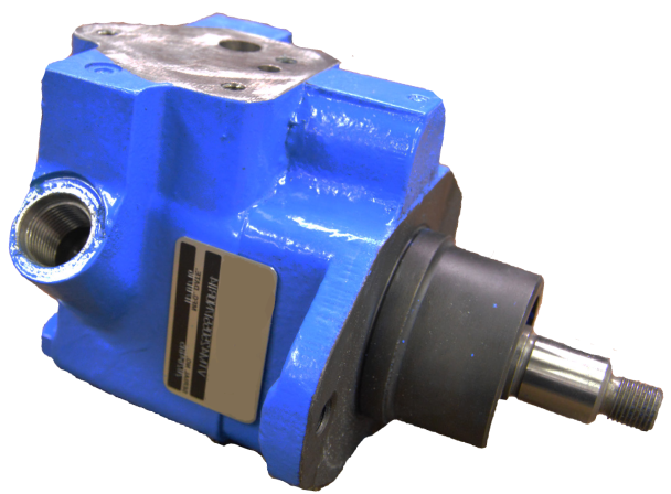
How to order
VTM 42 (A) 20 15 20 F 11 R 1 14
- VTM
- Vane pump
- 42
- Series
- A
- Mounting flange
- 20
- Ring size
- 15
- Controlled flow
- 20
- Relief valve setting
- F
- Reservoir filter
- 11
- Reservoir and manifold
- R
- Rotation
- 1
- Shaft
- 14
- Design
1. Vane pump
VTM — vane pump.
2. Series
42.
3. Mounting flange
A — SAE A mounting flange. Remanufactured only. Omit if not required.
4. Ring size — flow
SAE rated capacity at 1,200 r/min and 7 bar (100 psi).
| Code | Flow |
|---|---|
| 10 | 1.0 gpm |
| 15 | 1.5 gpm |
| 20 | 2.0 gpm |
| 40 | 4.0 gpm |
| 50 | 5.0 gpm |
| 60 | 6.0 gpm |
5. Controlled flow
At 1,500 r/min and 7 bar (100 psi).
| Code | Flow |
|---|---|
| 15 | 6 l/min (1.5 gpm) |
| 20 | 8 l/min (2 gpm) |
| 25 | 9.5 l/min (2.5 gpm) |
| 30 | 11 l/min (3 gpm) |
| 35 | 13 l/min (3.5 gpm) |
| 40 | 15 l/min (4 gpm) |
| 45 | 17 l/min (4.5 gpm) |
| 50 | 19 l/min (5 gpm) |
| 55 | 21 l/min (5.5 gpm) |
| 60 | 23 l/min (6 gpm) |
| 65 | 25 l/min (6.5 gpm) |
| 70 | 26.5 l/min (7 gpm) |
| 75 | 28 l/min (7.5 gpm) |
6. Relief valve setting
Cracking pressure.
| Code | Pressure |
|---|---|
| 05 | 500 psi |
| 07 | 750 psi |
| 10 | 1000 psi |
| 12 | 1250 psi |
| 15 | 1500 psi |
| 17 | 1750 psi |
| 20 | 2000 psi |
7. Reservoir filter
F — filter in place of the standard baffle. Omit if not required.
8. Reservoir and manifold
| Code | Description |
|---|---|
| 07 | 1147 mL (70 in³) reservoir. Omit for VTM42A |
| 11 | 1884 mL (115 in³) reservoir. Omit for VTM42A |
| MA | Manifold without bypass tube |
| MB | Manifold with bypass tube |
| MD | Manifold with 90° tank connection |
| ME | Cast manifold without bypass tube |
| MF | Cast manifold with bypass tube |
| NO | None (purchase closure only) |
9. Shaft rotation
| Code | Description |
|---|---|
| R | Right hand |
| L | Left hand |
10. Shaft type
| Code | Description |
|---|---|
| 1 | Threaded (VTM42 only) |
| 38 | Splined (VTM42A only) |
11. Design
Subject to change. Installation dimensions stay the same for designs –10 through –19.
The example shows 14.
*All manufacturer names and part numbers are used for reference only.
Operating specifications
| Series | Flow gpm at 1,200 r/min and 100 psi | Displacement in³/r | Max speed at 100 psi | Max speed at 1,500 psi | Max speed at 2,000 psi | Max pressure | Approx. weight |
|---|---|---|---|---|---|---|---|
| VTM42 | 1 | 0.21 | 7000 | 5000 | 4250 | 2000 psi | 14 lb |
| 1.5 | 0.31 | 7000 | 4500 | 4000 | |||
| 2 | 0.38 | 7000 | 4200 | 3800 | |||
| 4 | 0.79 | 7000 | 2800 | 2800 | |||
| 5 | 0.96 | 6000 | 2600 | 2300 | |||
| 6 | 1.18 | 5000 | 2500 | 2000 |
How to order
- 50V
- Series
- 100
- Capacity
- A
- Port connections
- 1
- Shaft
- C
- Outlet position
- 11
- Design
- 130
- Special modifications
- R
- Rotation
1. Series
50V — vane pump. SAE D mounting.
2. Capacity
| Code | Flow |
|---|---|
| 72 | 72 gpm |
| 85 | 85 gpm |
| 100 | 100 gpm |
| 109 | 109 gpm |
3. Port connections
Inlet and outlet ports.
| Code | Description |
|---|---|
| A | 4-bolt flange |
4. Shaft
| Code | Description |
|---|---|
| 1 | Straight keyed, 1.75" |
| 11 | Splined 1.75"-13T |
5. Outlet position
Viewed from the cover end.
| Code | Description |
|---|---|
| A | Outlet opposite the inlet |
| B | Outlet 90° counterclockwise from the inlet |
| C | Outlet in line with the inlet |
| D | Outlet 90° clockwise from the inlet |
6. Design
11.
7. Special modifications
| Code | Description |
|---|---|
| 130 | Flange mounting |
| 132 | With foot bracket |
8. Rotation
Viewed from the shaft end.
| Code | Description |
|---|---|
| R | Right hand |
| L | Left hand |
*All manufacturer names and part numbers are used for reference only.
Parts
| Part number | Description |
|---|---|
| V230642 | 50V shaft no. 1, straight keyed |
| V197878 | 50V shaft no. 11, splined |
| V922853 | 50V Buna seal kit, design 11 |
| V919256 | 50V Viton seal kit, design 11 |
| V923017 | 50V72 Buna cartridge kit, design 11 |
| V923018 | 50V85 Buna cartridge kit, design 11 |
| V923019 | 50V100 Buna cartridge kit, design 11 |
| V923020 | 50V109 Buna cartridge kit, design 11 |
Cartridge kits are also available in Viton. Every cartridge kit includes screws, pins, bushing, wear plate, ring, rotor and vane kit.
Vickers Style Hydraulic Vane Pumps: Types, Applications, Industries and Machinery
Vickers style hydraulic vane pumps are used in many industrial hydraulic systems where hydraulic flow is needed to drive cylinders, motors and other system components. Vane pumps come in different configurations, displacements and sizes to fit the needs of different equipment and applications.
At Technical Union (TU) we offer Vickers style hydraulic vane pump options, including different series and configurations such as VHO, VQ, V10, V20, V200, VTM42 and 50V.
If you need to replace an existing hydraulic pump, you can send us the pump part number, the nameplate information or the technical data you have so we can review a possible replacement option.
What is a hydraulic vane pump?
A vane pump uses a rotor and vanes that slide inside a ring or pumping element to generate the flow of hydraulic oil. As the rotor turns, the vanes form chambers of variable volume that carry the fluid from the pump inlet to the outlet.
Hydraulic vane pumps are used in systems that need a continuous supply of hydraulic oil to control different components of a machine.
Pump selection depends on factors such as:
- Pump displacement
- Required flow
- Operating pressure
- Rotation speed
- Mounting type
- Shaft configuration
- Hydraulic connections
- Direction of rotation
- Fluid used
- Specific machine requirements
For this reason, the model number or part number of the existing pump can be very important when looking for a replacement.
Vickers style vane pumps
The term Vickers is widely used to identify certain designs and configurations of hydraulic components. In the replacement market it is also common to find searches such as Vickers pump, Vickers hydraulic pump, Vickers vane pump and Vickers vane pump replacement.
TU options are aimed at applications that need a hydraulic vane pump compatible with the requirements of the system.
The series you can ask about include:
VHO and VQ
The VHO and VQ series are part of the vane pump families found in industrial hydraulic applications.
These pumps can be used in hydraulic systems that need a flow source to feed actuators and other hydraulic components.
When replacing a VHO or VQ pump, it is important to check the complete configuration and not only the series name.
V10 and V20
V10 and V20 vane pumps can be found in different hydraulic systems and machinery configurations.
When looking for a Vickers V10 pump or Vickers V20 pump, check the part number and the characteristics of the original pump to determine the right configuration.
V200
The V200 series is another hydraulic vane pump configuration that can be used in industrial systems.
To select a replacement V200 pump, review the characteristics of the existing pump and the requirements of the hydraulic system.
VTM42 and 50V
The VTM42 and 50V configurations can also be used as a reference when looking for certain hydraulic vane pumps.
When the equipment uses a pump identified by one of these numbers, the complete model number and the mounting configuration can help determine the right option.
Applications of hydraulic vane pumps
Hydraulic vane pumps can be used in a wide variety of hydraulic systems.
Applications include:
- Industrial hydraulic systems
- Hydraulic power units
- Hydraulic presses
- Machine tools
- Manufacturing equipment
- Industrial automation systems
- Material handling equipment
- Lifting systems
- Processing equipment
- Production machinery
- Hydraulic systems for manufacturing lines
- Industrial equipment with hydraulic cylinders
- Industrial equipment with hydraulic motors
The specific application determines the characteristics the pump must have.
Industries that use hydraulic systems
Hydraulic systems are used in practically every sector where power has to be transmitted through hydraulic pressure and flow.
Hydraulic vane pumps can be found in equipment used in industries such as:
Industrial manufacturing
Production and manufacturing machines can use hydraulic systems to drive cylinders, clamping mechanisms, presses and other actuators.
Metalworking
Equipment used to work, form or process metals can include hydraulic systems to generate high forces and control movements.
Plastics
Machines used to process and manufacture plastic products can include hydraulic components for different machine functions.
Automotive
Production lines and certain equipment used in vehicle manufacturing and processing can use hydraulic systems for movement, clamping and automation.
Material handling
Industrial equipment that lifts, moves, positions or clamps materials can use hydraulic pumps to feed cylinders and motors.
Construction
Certain construction equipment uses hydraulic systems to control cylinders, motors and other mechanisms. The specific pump must be selected according to the requirements of the equipment.
Agriculture
Some agricultural machines and equipment include hydraulic systems for lifting, positioning and drive functions.
Mining and materials processing
Equipment used for extraction, processing and handling of materials can use hydraulic systems to provide force and controlled movement.
Machines that can use hydraulic vane pumps
Depending on the design of the hydraulic system, vane pumps can be found in different types of machinery.
Some examples include:
- Hydraulic presses
- Machine tools
- Manufacturing machines
- Automation equipment
- Processing machines
- Material handling equipment
- Lifting systems
- Hydraulic power units
- Industrial production equipment
- Agricultural machinery
- Construction equipment
- Metal processing equipment
- Machinery for manufacturing plastic products
- Equipment used on production lines
A vane pump on a machine does not mean that any pump of the same series can be installed directly. The replacement must be checked against the characteristics of the pump and of the system.
Replacing a Vickers hydraulic pump
When a hydraulic pump has to be replaced, users often have an installed pump but do not know all of its specifications.
In these cases, the part number can be the best starting point.
To request a replacement review, you can provide:
- Part number
- Brand or identification of the pump
- Pump model
- Photos of the nameplate
- Displacement, if available
- Operating pressure
- Required flow
- RPM
- Mounting type
- Shaft type
- Inlet and outlet connections
- Direction of rotation
With this information it is possible to review the characteristics needed to find a pump that matches the application.
Looking for a replacement Vickers vane pump?
If you are looking for a Vickers hydraulic vane pump, a VHO, VQ, V10, V20, V200, VTM42 or 50V pump, send us the part number of the pump you currently use.
You can also provide photos, nameplate information or the specifications you have.
Technical Union (TU) can review your information and help you identify a hydraulic pump option for your application.
Request a quote by sending the pump model or part number, the application and, when possible, the pressure, flow and speed requirements.
Hydraulic vane pumps for industrial applications
Vickers style vane pumps can be used in a wide variety of hydraulic systems. The right selection depends on the characteristics of the machine and the requirements of the hydraulic circuit.
To get information about a specific pump, ask about the series, model or part number you need.